
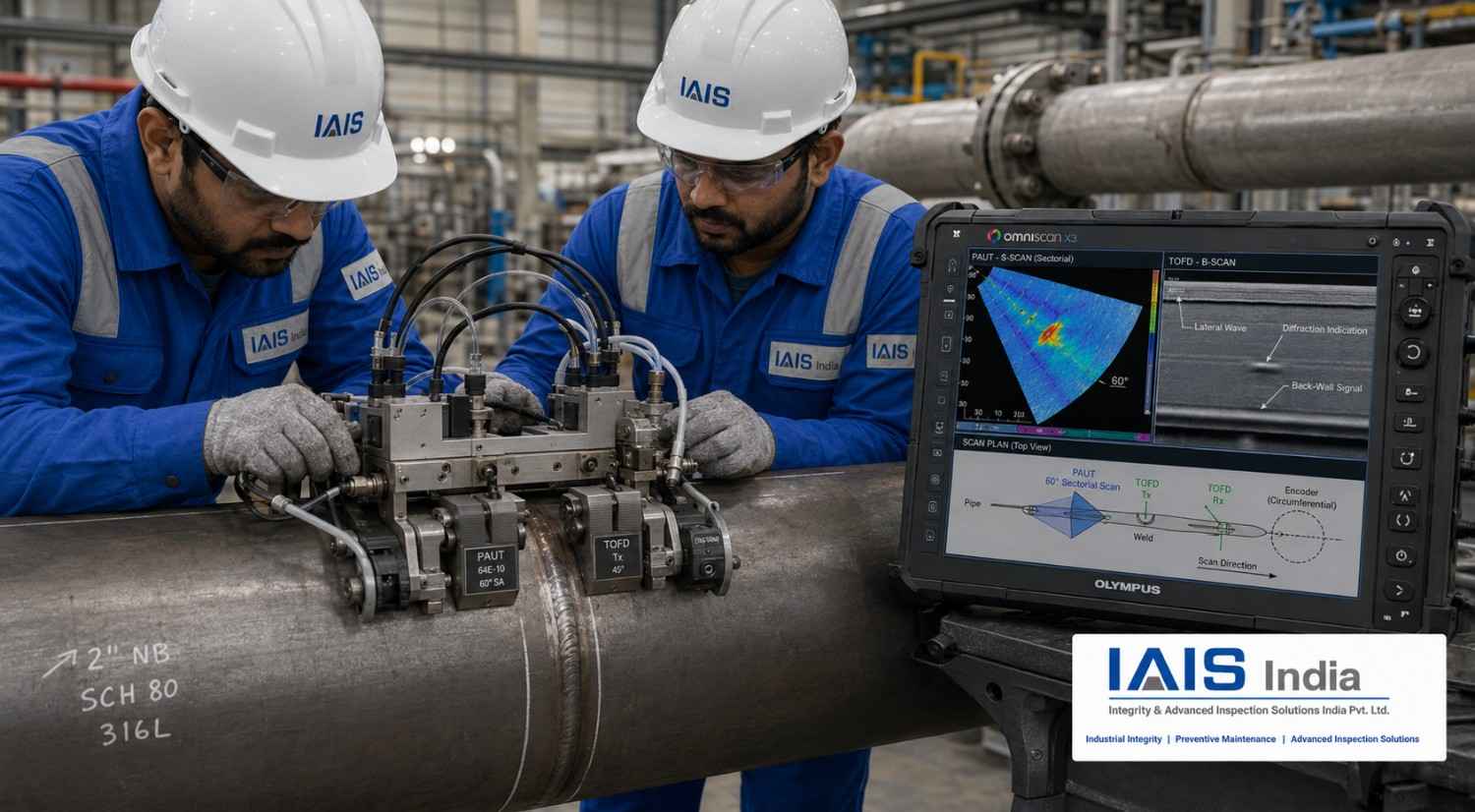
Combined PAUT and TOFD Weld Inspection
Phased Array Ultrasonic Testing (PAUT) and Time of Flight Diffraction (TOFD) are advanced ultrasonic inspection techniques used to detect and evaluate discontinuities in welded components.
The two techniques operate differently and offer complementary inspection capabilities:
➤ PAUT uses electronically controlled beams to inspect the weld from multiple angles.
➤ TOFD uses diffracted ultrasonic signals to detect and size discontinuities through the component thickness.
When applied together under an approved procedure, PAUT and TOFD can provide comprehensive weld-volume coverage, reliable defect detection, improved sizing information and permanent digital inspection records.
What Is PAUT?
PAUT uses a probe containing multiple ultrasonic elements. By applying controlled time delays to these elements, the instrument can electronically steer and focus the sound beam.
PAUT can generate:
➤ Sectorial scans
➤ Linear scans
➤ Multiple inspection angles
➤ Focused beams at selected depths
➤ A-scan, S-scan, B-scan and C-scan views
➤ Encoded inspection data
This technology helps inspectors examine the weld root, fusion faces, weld body and heat-affected zone.
What Is TOFD?
TOFD uses separate transmitting and receiving probes positioned on opposite sides of the weld.
The transmitting probe sends a wide ultrasonic beam through the inspection volume. When the beam encounters the tip of a discontinuity, part of the sound energy is diffracted.
The receiving probe collects signals that may include:
➤ Lateral wave
➤ Back-wall reflection
➤ Upper-tip diffraction
➤ Lower-tip diffraction
➤ Mode-converted signals
The time difference between these signals can be used to determine the position and through-wall height of a discontinuity.
Why Combine PAUT and TOFD?
PAUT and TOFD respond to discontinuities using different ultrasonic principles.
PAUT is generally effective for detecting and characterizing reflectors based on their orientation and reflected signal response. TOFD is based primarily on signals diffracted from the ends of discontinuities.
Combining the methods can provide:
➤ Multi-angle weld inspection
➤ Improved detection of planar discontinuities
➤ Reliable through-wall sizing for suitable defects
➤ Better coverage of the weld volume
➤ Additional confirmation of reportable indications
➤ Encoded and traceable inspection data
➤ Greater confidence in defect evaluation
Neither technique should be treated as automatically complete for every weld. The combined inspection must be designed according to the material, thickness, joint geometry, expected defect orientation and applicable code.
PAUT and TOFD Comparison
|
Inspection factor |
PAUT | TOFD |
| Basic principle | Reflection of steered and focused ultrasonic beams |
Diffraction of sound from discontinuity tips |
|
Probe arrangement |
Single or multiple phased-array probes |
Separate transmitter and receiver probes |
|
Data presentation |
A-scan, S-scan, B-scan and C-scan | Grey-scale B-scan image |
| Defect detection | Highly dependent on beam and defect orientation |
Less dependent on defect orientation for suitable diffracting defects |
|
Defect characterization |
Useful for location and characterization | Primarily used for detection and sizing |
| Through-wall sizing | Possible with approved sizing techniques |
Strong capability for suitable defects |
|
Near-surface coverage |
Can be optimized with suitable beams and probes | Restricted by lateral-wave and back-wall dead zones |
| Weld coverage | Multiple angles can cover different weld areas |
Wide beam covers a large part of the weld thickness |
|
Data recording |
Full encoded recording available | Full encoded recording available |
| Main contribution | Detection, imaging and characterization |
Through-wall sizing and confirmation |
Typical Combined Inspection Arrangement
A combined scanner may carry:
➤ One PAUT probe on each side of the weld
➤ One TOFD transmitting probe
➤ One TOFD receiving probe
➤ Position encoder
➤ Magnetic or chain-based scanner assembly
➤ Couplant delivery system
➤ Guide mechanism for maintaining probe separation
The actual probe configuration depends on the component diameter, thickness, weld design and required inspection coverage.
For some applications, PAUT and TOFD scans may be performed separately instead of using a single combined scanner.
Welds Suitable for PAUT and TOFD
Combined PAUT and TOFD inspection can be applied to:
➤ Process-piping welds
➤ Pipeline girth welds
➤ Pressure-vessel welds
➤ Storage-tank welds
➤ Boiler welds
➤ Structural welds
➤ Heavy-wall fabrication welds
➤ Longitudinal and circumferential welds
➤ Repair welds
➤ In-service weld examinations
Feasibility must be confirmed for:
➤ Small-diameter pipes
➤ Thin-wall components
➤ Nozzle welds
➤ Branch connections
➤ Austenitic welds
➤ Dissimilar-metal welds
➤ Complex geometries
➤ Components with restricted scanning access
Discontinuities Detectable
Subject to the approved inspection technique, combined PAUT and TOFD may detect:
➤ Lack of sidewall fusion
➤ Lack of root fusion
➤ Incomplete penetration
➤ Cracks
➤ Slag inclusions
➤ Service-induced cracking
➤ Weld-repair defects
➤ Planar embedded discontinuities
➤ Certain volumetric discontinuities
➤ Other weld-related imperfections
PAUT is commonly useful for identifying the reflector’s position and orientation. TOFD can assist in determining its through-wall extent when clear upper- and lower-tip signals are available.
Near-Surface and Back-Wall Limitations of TOFD
TOFD has inherent dead zones near the scanning surface and back wall.
Lateral-Wave Dead Zone
The lateral wave travels close to the inspection surface. Signals from shallow discontinuities can be hidden by this response.
Back-Wall Dead Zone
Signals from discontinuities close to the far surface may interfere with the back-wall response.
PAUT can provide supplementary coverage of these areas using suitable beam angles and probe arrangements. This is one of the primary reasons PAUT and TOFD are frequently combined.
Combined Inspection Procedure
1. Technical Review
The inspection team reviews:
➤ Component drawing
➤ Weld preparation
➤ Material specification
➤ Diameter and wall thickness
➤ Expected discontinuity locations
➤ Scanning-surface condition
➤ Available access
➤ Applicable code
➤ Acceptance criteria
2. Scan-Plan Preparation
The PAUT scan plan should demonstrate coverage of:
➤ Weld root
➤ Fusion faces
➤ Weld body
➤ Heat-affected zone
➤ Near-surface areas
➤ Far-surface areas
The TOFD plan determines:
➤ Probe-centre separation
➤ Probe frequency
➤ Refracted angle
➤ Beam intersection point
➤ Coverage zones
➤ Number of TOFD groups
Thick components may require multiple TOFD groups to cover different depth zones adequately.
3. Calibration-Block Selection
A suitable calibration block is used to verify:
➤ Material velocity
➤ Wedge delay
➤ Sensitivity
➤ Time base
➤ Probe separation
➤ Encoder response
➤ PAUT focal laws
➤ TOFD lateral wave
➤ TOFD back-wall signal
➤ Reference reflectors
Project-specific blocks may be required for complex geometries or critical inspections.
4. System Calibration
Calibration and verification are completed in accordance with the approved procedure.
The inspector confirms:
➤ PAUT beam angles
➤Index offset
➤ Sensitivity
➤ Time-corrected gain
➤ TOFD time base
➤ Probe-centre separation
➤ Encoder accuracy
➤ Data-recording range
5.Encoded Scanning
The scanner moves along the weld while the encoder records its position. PAUT and TOFD data are acquired and stored digitally.
Stable coupling, consistent scanner alignment and accurate weld tracking are essential during data collection.
6. Data Analysis
PAUT and TOFD data are reviewed together to determine:
➤ Indication position
➤ Indication length
➤ Through-wall location
➤ Estimated through-wall height
➤ Relationship to the weld profile
➤ Signal characteristics
➤ Applicable acceptance criteria
7. Reporting
The final report may include:
➤ Inspection procedure reference
➤ Scan-plan details
➤ Equipment configuration
➤ Calibration information
➤ Weld identification
➤ Inspection coverage
➤ PAUT and TOFD images
➤ Indication table
➤ Sizing results
➤ Acceptance status
➤ Inspection summary
Advantages of Combined PAUT and TOFD
Comprehensive Weld Coverage
PAUT covers the weld using multiple directional beams, while TOFD provides broad through-wall coverage.
Improved Defect Sizing
TOFD can provide through-wall sizing when clear tip-diffracted signals are obtained. PAUT can support indication localization and characterization.
Better Near-Surface Coverage
PAUT can supplement the areas affected by TOFD’s lateral-wave and back-wall dead zones.
Digital Inspection Records
Both methods can produce permanent encoded data for review, audit and future comparison.
Immediate Results
Inspection data can normally be analysed on-site without film processing.
No Ionising Radiation
PAUT and TOFD use ultrasonic energy and do not require radiation exclusion zones.
Repeatable Inspection
Encoded scanning improves positional accuracy and repeatability for future monitoring.
Limitations and Technical Considerations
Combined inspection performance can be affected by:
➤ Restricted scanning access
➤ Rough or coated surfaces
➤ Poor ultrasonic coupling
➤ Complex weld profiles
➤ Small-diameter pipe curvature
➤ Thin-wall components
➤ Coarse-grained materials
➤ Austenitic or dissimilar-metal welds
➤ Incorrect weld dimensions
➤ Inadequate calibration blocks
➤ Inappropriate probe selection
➤ Scanner misalignment
➤ Poorly designed scan plans
A technical feasibility study or procedure demonstration may be required before inspecting critical or unusual components.
Applicable Standards and Codes
PAUT and TOFD examinations may be performed according to relevant requirements from:
➤ ASME Boiler and Pressure Vessel Code, Section V
➤ ISO 13588
➤ ISO 16828
➤ ISO 15626
➤ ISO 17640
➤ ISO 4761
➤ ISO 20601
➤ ISO 22825
➤ API 1104
➤ Applicable construction codes
➤ Client-approved specifications and procedures
The applicable edition, qualification requirements and acceptance criteria must be confirmed before starting the inspection.
Can Combined PAUT and TOFD Replace Radiography?
Combined PAUT and TOFD may be accepted as an alternative to radiographic testing for certain welds when permitted by the applicable construction code and approved by the client or engineering authority.
Before substitution, the project should confirm:
➤ Code acceptance
➤ Written client approval
➤ Qualified inspection procedure
➤ Adequate scan-plan coverage
➤ Suitable calibration blocks
➤ Personnel qualifications
➤ Demonstration requirements
➤ Applicable acceptance criteria
➤ Data-recording and reporting requirements
The replacement of radiography must never be assumed without formal technical approval.
Our PAUT and TOFD Services
Integrity & Advanced Inspection Solutions India Private Limited provides:
➤ Combined PAUT and TOFD inspection
➤ Encoded weld scanning
➤ Pipeline girth-weld inspection
➤ Pressure-vessel weld inspection
➤ Process-piping inspection
➤ Shutdown inspection support
➤ Procedure preparation
➤ Scan-plan development
➤ Calibration-block design
➤ Inspection feasibility studies
➤ On-site data analysis
➤ Detailed weld-wise reporting
➤ Domestic and international mobilization
Information Required for a Proposal
Please provide:
➤ Component or weld drawing
➤ Material specification
➤ Diameter and wall thickness
➤ Weld joint configuration
➤ Total number and length of welds
➤ Applicable construction code
➤ Acceptance criteria
➤ Inspection location
➤ Surface-access details
➤ Project schedule
➤ Required reporting format
Our technical team will review the application and recommend the appropriate PAUT, TOFD or combined inspection configuration.