
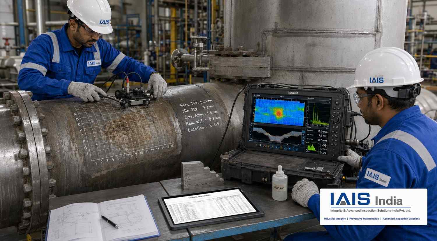
PAUT Corrosion Mapping Services
Phased Array Ultrasonic Testing can be used to map corrosion, erosion and localized wall-thickness loss in pipes, pressure vessels, tanks and other industrial components.
Unlike isolated thickness readings, encoded PAUT corrosion mapping collects ultrasonic information across a defined surface area. The recorded data can then be presented as colour-coded thickness maps, cross-sectional views and minimum-thickness results.
This provides engineers with a clearer understanding of the location, extent and severity of material loss.
What Is Corrosion Mapping?
Corrosion mapping is an ultrasonic examination used to measure and record remaining material thickness across a selected inspection area.
The results can help identify:
➤ General wall thinning
➤ Localized corrosion
➤ Internal pitting
➤ Erosion
➤ Flow-accelerated corrosion
➤ Corrosion beneath deposits
➤ Corrosion around welds
➤ Material loss near nozzles
➤ Minimum remaining-wall locations
➤ Changes between periodic inspections
Corrosion mapping supplies inspection data. Determining whether the component is fit for continued service requires a separate engineering assessment using the applicable design or fitness-for-service criteria.
How PAUT Corrosion Mapping Works
A phased-array probe contains multiple ultrasonic elements. The system activates groups of these elements in a programmed sequence to cover a strip of material beneath the probe.
When the probe is moved across the component using an encoded scanner, the system records:
➤ Ultrasonic response
➤ Probe position
➤ Material thickness
➤ Back-wall condition
➤ Scan length
➤ Coverage area
Software converts the collected information into visual thickness maps and sectional views.
PAUT Corrosion Mapping vs Manual Thickness Measurement
|
Inspection factor |
Manual UT thickness readings | PAUT corrosion mapping |
| Measurement approach | Individual selected locations |
Encoded coverage across a defined area |
|
Data density |
Limited point readings | Large number of recorded readings |
| Localized corrosion | May be missed between grid points |
Better probability of locating wall loss within the scanned area |
|
Data presentation |
Thickness table or grid | Colour map, B-scan, C-scan and thickness table |
| Positional recording | Manually marked |
Encoder-linked position data |
|
Repeatability |
Depends on relocating the same points |
Scan files and reference positions support repeat examination |
|
Inspection speed |
Efficient for a small number of readings | Efficient for larger-area detailed mapping |
| Equipment requirement | Basic thickness gauge |
PAUT instrument, probe and encoded scanner |
|
Surface access |
Small measurement locations |
Continuous scanner-access area required |
Manual UT remains valuable for general thickness surveys and confirmation readings. PAUT mapping is preferred when detailed coverage and permanent encoded data are required.
Typical Applications
PAUT corrosion mapping can be applied to:
➤ Process piping
➤ Pipelines
➤ Pressure vessels
➤ Storage tanks
➤ Boiler components
➤ Heat-exchanger shells
➤ Columns and reactors
➤ Offshore structures
➤ Marine components
➤ Elbows and bends
➤ Nozzle areas
➤ Injection points
➤ Pipe supports and contact areas
➤ Areas affected by erosion or impingement
Common Damage Mechanisms
General Corrosion
Relatively uniform material loss occurring across a wider surface area.
Localized Corrosion
Concentrated metal loss affecting a smaller region of the component.
Pitting
Individual or grouped cavities that may produce rapid local thickness reduction.
Erosion
Material loss caused by high-velocity fluids, particles or turbulent flow.
Flow-Accelerated Corrosion
Accelerated wall thinning caused by the combined effects of flow, material and fluid chemistry.
Impingement Damage
Localized erosion or corrosion caused by fluid striking the component surface.
Corrosion Near Welds
Wall loss may occur in the weld, heat-affected zone or adjacent parent material due to operating conditions or material differences.
Corrosion Under Pipe Supports
Moisture and contamination trapped near pipe supports can cause localized external corrosion.
PAUT suitability depends on whether the probe and scanner can access and couple to the affected surface.
Inspection Planning
Before corrosion mapping, the inspection team should review:
➤ Component drawings
➤ Nominal thickness
➤ Material specification
➤ Outside diameter
➤ Expected corrosion mechanism
➤ Previous inspection results
➤ Operating temperature
➤ Surface condition
➤ Coating thickness
➤ Required mapping area
➤ Location-reference system
➤ Minimum reporting resolution
➤ Engineering assessment requirements
The mapping area should be selected based on the expected damage pattern, not only ease of access.
Surface Preparation
The inspection surface should allow stable probe movement and ultrasonic coupling.
Surface preparation may include removing:
➤ Loose rust
➤ Scale
➤ Dirt and deposits
➤ Flaking paint
➤ Weld spatter
➤ Sharp surface projections
➤ Excessive coating
➤ Oil or grease
Some sound, well-bonded coatings may be inspectable after technical verification. Rough, loose or multi-layer coatings can affect coupling and thickness accuracy.
Calibration Requirements
The PAUT system should be calibrated using a reference block representative of the inspected material and thickness range.
Calibration may include:
➤ Material-velocity calibration
➤ Wedge-delay calibration
➤ Sensitivity verification
➤ Thickness calibration
➤ Encoder calibration
➤ Zero-offset verification
➤ Minimum and maximum thickness range
➤ Reference-area verification
Calibration should be checked at specified intervals and after any change that could affect the inspection results.
Encoded Data Acquisition
An encoded scanner records the probe position while moving across the component.
The scanning system may use:
➤ One-axis linear scanning
➤ Two-axis raster scanning
➤ Magnetic-wheel scanners
➤ Chain scanners
➤ Manual encoded frames
➤ Automated scanners
➤ Curved-surface scanner assemblies
The scan increment and index resolution should be selected according to the required probability of detecting localized wall loss.
Corrosion-Mapping Data Views
A-Scan
Displays ultrasonic amplitude against sound path. It is used to verify signal quality and evaluate individual locations.
B-Scan
Provides a side view showing the thickness profile along the scan direction.
C-Scan
Provides a plan view of the inspected area. Colours commonly represent different remaining-wall thickness ranges.
Thickness Map
Shows the measured thickness distribution and highlights minimum-thickness areas.
Colour ranges must be clearly defined in the report. A specific colour does not automatically mean that the component is acceptable or rejectable.
Minimum Remaining-Wall Thickness
PAUT mapping can identify the lowest recorded thickness within the scanned area.
The inspection report may include:
➤ Nominal thickness
➤ Measured minimum thickness
➤ Location of minimum thickness
➤ Average thickness
➤ Size of the affected area
➤ Thickness ranges
➤ Percentage of recorded wall loss
➤ Scan dimensions and orientation
Inspection Resolution
Corrosion-mapping resolution depends on:
➤ Probe element size
➤ Active aperture
➤ Ultrasonic frequency
➤ Scan speed
➤ Encoder resolution
➤ Index increment
➤ Beam coverage
➤ Material surface condition
➤ Corrosion morphology
➤ Signal-processing settings
A coarse scan may identify general thinning but miss narrow pits. Detailed pitting assessment may require a finer scan, focused configuration or supplementary manual measurements.
Limitations of PAUT Corrosion Mapping
Potential limitations include:
➤ Rough or heavily corroded scanning surfaces
➤ Poor probe coupling
➤ Thick or disbonded coatings
➤ Complex component geometry
➤ Limited scanner access
➤ Very small isolated pits
➤ Closely spaced interface signals
➤ Laminated materials
➤ Coarse-grained material
➤ High-temperature surfaces
➤ Deposits affecting back-wall response
➤ Incorrect material velocity
➤ Areas located directly beneath supports or attachments
The reported results should clearly identify inaccessible areas, incomplete coverage and data-quality limitations.
Corrosion Mapping on Curved Components
Pipes, elbows and nozzles may require:
➤ Contoured wedges
➤ Flexible probe arrangements
➤ Chain or magnetic scanners
➤ Diameter-specific calibration
➤ Multiple scanning directions
➤ Customized scanner frames
Curvature should be included in inspection planning because it can affect probe contact, beam direction and positional accuracy.
High-Temperature Corrosion Mapping
Inspection of hot components requires special consideration.
The technical team must review:
➤ Surface temperature
➤ Probe temperature rating
➤ Wedge material
➤ Couplant temperature rating
➤ Calibration temperature
➤ Thermal expansion
➤ Safe probe-contact duration
➤ Operator protection
➤ Scanner suitability
Standard probes and wedges must not be used above their specified temperature limits.
Repeat Inspection and Condition Monitoring
Encoded corrosion maps can provide a baseline for future inspection.
Repeated examinations may help determine:
➤ Corrosion growth
➤ Erosion progression
➤ Change in minimum thickness
➤ Expansion of the affected area
➤ Need for repair or replacement
➤ Suitability of the inspection interval
Reliable comparison requires consistent scan locations, surface references, equipment settings and reporting formats.
PAUT Mapping and Fitness-for-Service Assessment
PAUT provides measured inspection data but does not independently determine component fitness.
Engineering evaluation may consider:
➤ Minimum measured thickness
➤ Design pressure and temperature
➤ Material properties
➤ Component dimensions
➤ Corrosion extent
➤ Remaining ligament
➤ Local stress concentration
➤ Corrosion rate
➤ ➤ Previous inspection history
➤ Applicable design or fitness-for-service code
An authorized inspection or engineering professional should complete the final remaining-life or fitness-for-service assessment.
PAUT Corrosion Mapping vs Pulsed Eddy Current
PAUT generally requires direct surface access and suitable ultrasonic coupling. It provides detailed local thickness mapping where the surface is accessible.
Pulsed Eddy Current can screen ferromagnetic components through insulation, coatings and protective materials, subject to technique limitations. It is commonly used to identify areas requiring further examination.
A practical inspection programme may use:
1. PEC for broader-area screening.
2. PAUT or conventional UT for detailed thickness confirmation.
3. Engineering evaluation of the measured wall loss.
Typical Deliverables
A corrosion-mapping report may include:
➤ Component identification
➤ Inspection-area drawing
➤ Grid and coordinate references
➤ Equipment and probe details
➤ Calibration records
➤ Scan resolution
➤ Nominal thickness
➤ Minimum recorded thickness
➤ Colour-coded C-scan maps
➤ B-scan profiles
➤ Thickness tables
➤ Areas of localized wall loss
➤ Inaccessible areas
➤ Inspection limitations
➤ Summary of findings
Applicable Standards
Corrosion mapping and thickness assessment may be performed with reference to:
➤ Applicable ASME requirements
➤ ISO ultrasonic-testing requirements
➤ API inspection standards
➤ Client inspection procedures
➤ Plant-specific corrosion-monitoring programmes
➤ Approved written procedures
➤ Applicable fitness-for-service methodologies
The governing procedure, reporting threshold and acceptance criteria should be agreed before inspection.
Our PAUT Corrosion-Mapping Capabilities
Integrity & Advanced Inspection Solutions India Private Limited provides:
➤ Encoded PAUT corrosion mapping
➤ Pipeline and process-piping inspection
➤ Pressure-vessel thickness mapping
➤ Tank and structural-component mapping
➤ Elbow and bend inspection
➤ Weld-area corrosion mapping
➤ Manual UT confirmation
➤ Pulsed Eddy Current screening support
➤ Customized scanners and wedges
➤ Baseline and repeat inspection
➤ Digital data analysis
➤ Colour-coded thickness reports
➤ Engineering-data preparation
Information Required for a Proposal
Please provide:
➤ Component type
➤ Material specification
➤ Nominal thickness
➤ Diameter or surface dimensions
➤ Total mapping area
➤ Surface condition
➤ Coating or insulation details
➤ Operating temperature
➤ Expected damage mechanism
➤ Previous thickness records
➤ Required scan resolution
➤ Site location
➤ Inspection schedule
➤ Reporting requirements
Request a Corrosion-Mapping Proposal
Our technical team can review the component condition and recommend PAUT mapping, conventional UT, Pulsed Eddy Current or a combined inspection approach based on the required coverage and inspection objective.