
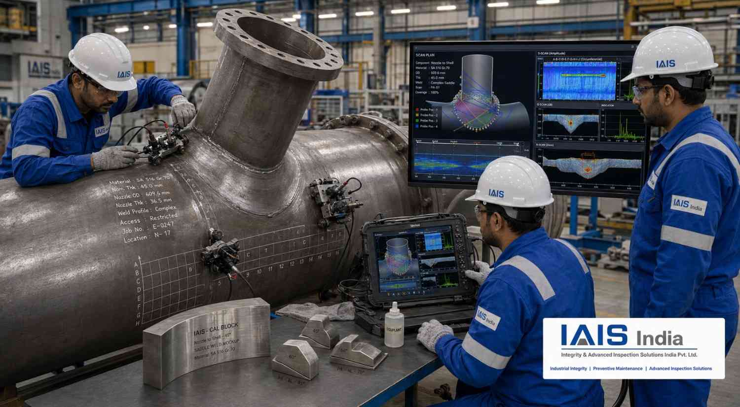
PAUT Inspection of Complex-Geometry Welds
Phased Array Ultrasonic Testing can be applied to many weld configurations that are difficult to inspect using conventional ultrasonic testing or radiography.
Complex welds may contain curved surfaces, variable thicknesses, changing beam paths, restricted probe access and geometric reflectors. These factors make inspection planning and data interpretation significantly more challenging than the examination of a standard plate or pipe butt weld.
For these applications, PAUT should be supported by a detailed feasibility assessment, weld-specific scan plan, suitable probes and wedges, representative calibration blocks and a validated written procedure.
What Is a Complex-Geometry Weld?
A complex-geometry weld is any welded connection where the shape, access or material condition prevents the use of a standard inspection setup.
Examples include:
➤ Nozzle-to-shell welds
➤ Branch connections
➤ Socket welds
➤ Fillet welds
➤ Flange-to-pipe welds
➤ Elbow welds
➤ Reducer welds
➤ Tee connections
➤ Set-on and set-in nozzles
➤ Saddle welds
➤ Partial-penetration welds
➤ Dissimilar-metal welds
➤ Weld overlays and cladding
➤ Repair welds
➤ Components with variable thickness
➤ Restricted-access welds
Not every complex weld is fully inspectable using PAUT. Inspection feasibility and achievable coverage must be established before making a technical commitment.
Why Are Complex Welds Difficult to Inspect?
Changing Component Geometry
Curved, tapered or irregular surfaces change the direction and travel distance of the ultrasonic beam.
Restricted Probe Access
Flanges, supports, adjacent pipes, insulation attachments and structural obstructions may prevent the probe from reaching the required scanning position.
Variable Wall Thickness
Thickness changes can produce complex reflections and make indication positioning more difficult.
Irregular Weld Profiles
Weld crowns, root reinforcement, counterbores and internal transitions can generate geometric signals that may resemble discontinuities.
Limited Beam Orientation
Some fusion faces or expected defect locations cannot be reached from an available scanning surface.
Material Attenuation
Austenitic stainless steel, nickel alloys, cast materials and coarse-grained structures can scatter or attenuate ultrasonic energy.
Mode Conversion
Sound reflecting from curved or angled surfaces can convert between longitudinal and shear-wave modes, producing additional signals.
Typical PAUT Applications
Nozzle-to-Shell Welds
Nozzle welds can include changing curvature, different component thicknesses and multiple fusion faces.
Inspection may require scanning from:
➤ Nozzle outside surface
➤ Nozzle bore
➤ Vessel shell surface
➤ Internal vessel surface
➤ More than one probe orientation
The achievable coverage depends on the nozzle diameter, shell thickness, weld preparation and accessibility.
Branch Connections
Set-on and set-in branch connections can be challenging because the weld geometry changes continuously around the circumference.
A single setup may not provide equal coverage at every clock position. Multiple scan plans or zone-specific configurations may be required.
Flange-to-Pipe Welds
The flange face or hub can restrict the available scanning distance. Compact probes, miniature wedges or scanning from the pipe side may be necessary.
Fillet Welds
Fillet welds are difficult to inspect volumetrically because their geometry produces strong reflections and access may be available from only one component.
PAUT feasibility depends on:
➤ Fillet size
➤ Weld penetration
➤ Plate or pipe thickness
➤ Scanning access
➤ Expected defect orientation
➤ Required examination volume
Elbows and Reducers
Curvature and changing thickness can distort the ultrasonic beam. Customized contoured wedges and accurate component profiles may be required.
Repair Welds
Repair excavations and local build-up can create irregular profiles. The inspection plan should include the repair dimensions, original component geometry and expected discontinuity locations.
Importance of Accurate Drawings
Complex-geometry PAUT depends heavily on accurate dimensional information.
The client should provide:
➤ Fabrication drawing
➤ Weld-joint design
➤ As-built dimensions
➤ Weld bevel angle
➤ Root gap and land
➤ Material thicknesses
➤ Counterbore details
➤ Weld-cap dimensions
➤ Internal surface profile
➤ Available scanning surfaces
➤ Nearby obstructions
Nominal drawings may not accurately represent an existing or repaired component. On-site dimensional verification may therefore be necessary.
PAUT Feasibility Assessment
A technical feasibility review should be completed before finalizing the inspection scope.
The review determines:
➤ Whether the required weld volume is ultrasonically accessible
➤ Suitable scanning surfaces
➤ Required probe types
➤ Wedge configuration
➤ Beam angles and wave modes
➤ Number of scanning positions
➤ Expected coverage limitations
➤ Calibration-block requirements
➤ Need for procedure demonstration
➤ Requirement for complementary NDT methods
The result should clearly distinguish between:
➤ Fully covered areas
➤ Partially covered areas
➤ Non-accessible areas
➤ Areas requiring supplementary inspection
Scan-Plan Development
A weld-specific scan plan models the relationship between the probe, ultrasonic beam, component geometry and examination volume.
A complex-weld scan plan may include:
➤ Multiple probe positions
➤ Multiple refracted angles
➤ Longitudinal and shear-wave configurations
➤ Half-skip and full-skip paths
➤ Beam focusing at different depths
➤ Separate focal laws for individual weld zones
➤ Scanning from opposing surfaces
➤ Coverage of fusion faces
➤ Root and near-surface coverage
➤ Identification of geometric reflectors
➤ Known inspection limitations
For connections where geometry changes around the circumference, separate scan plans may be required for different clock positions.
Probe and Wedge Selection
Complex welds may require:
➤ Small-footprint PAUT probes
➤ Low-frequency probes
➤ High-frequency probes for thin materials
➤ Linear-array probes
➤ Dual-matrix array probes
➤ Customized flat wedges
➤ Contoured outside-diameter wedges
➤ Inside-diameter wedges
➤ Curved wedges
➤ Low-profile scanner assemblies
➤ Immersion or water-column arrangements
Probe selection depends on the material, sound path, expected defect orientation and available access.
Customized Wedges
A standard flat wedge may not provide stable coupling on a curved or restricted surface.
A customized wedge can be designed for:
➤ Outside-diameter curvature
➤ Inside-diameter curvature
➤ Convex surfaces
➤ Concave surfaces
➤ Restricted-clearance applications
➤ Specific roof angles
➤ Particular refracted angles
➤Improved probe positioning
The wedge design must consider ultrasonic performance, not only mechanical fit.
Representative Calibration Blocks
Standard calibration blocks may not adequately represent a complex component.
A customized calibration block may be required to reproduce:
➤ Material specification
➤ Thickness
➤ Surface curvature
➤ Weld geometry
➤ Cladding or overlay
➤ Counterbore
➤ Representative reflectors
➤ Expected defect locations
➤ Sound attenuation
Reference reflectors may include side-drilled holes, notches or other code-approved reflectors.
For critical inspections, a demonstration block containing realistic defects may be used to verify detection and sizing performance.
Inspection Procedure
1. Document Review
Review the drawing, material, weld design, applicable code and acceptance criteria.
2. Dimensional Verification
Measure the actual component profile, thickness, weld cap and available scanning space.
3. Feasibility Study
Evaluate sound paths, expected defect orientations and accessible scanning positions.
4. Scan-Plan Preparation
Prepare weld-specific focal laws and demonstrate theoretical examination coverage.
5. Technique Demonstration
Confirm the proposed technique using a suitable reference or demonstration block.
6. Surface Preparation
Ensure the scanning surface supports stable probe movement and ultrasonic coupling.
7. Data Acquisition
Perform manual or encoded scanning from all required positions.
8. Data Analysis
Differentiate relevant discontinuity responses from component-geometry and mode-conversion signals.
9. Reporting
Document the inspection results together with coverage and technical limitations.
Manual vs Encoded PAUT
Manual PAUT
Manual scanning may be more practical for irregular components and highly restricted areas. It provides flexibility but depends heavily on inspector-controlled probe positioning.
Encoded PAUT
Encoded inspection provides better positional traceability and permanent data recording. However, a scanner may not follow rapidly changing surfaces or fit within restricted spaces.
Semi-encoded arrangements, miniature encoders or customized scanner guides may be used when full mechanization is impractical.
Geometric Signals vs Defect Signals
Complex components can produce reflections from:
➤ Weld root
➤ Counterbore
➤ Internal radius
➤ Flange face
➤ Nozzle bore
➤ Component back wall
➤ Weld cap
➤ Thickness transition
➤Cladding interface
➤Machined surface
These signals can be misinterpreted as defects if the actual geometry is not understood.
Reliable evaluation may require:
➤ Probe movement analysis
➤ Multiple beam angles
➤ Scanning from opposite directions
➤ Comparison with drawings
➤ Reference-block responses
➤ Additional conventional UT
➤ Surface examination
➤ Repeat scans using different probe configurations
Austenitic and Dissimilar-Metal Welds
Austenitic stainless steel and nickel-alloy welds can contain coarse and directionally oriented grains that scatter and redirect ultrasonic energy.
Inspection may require:
➤ Lower frequencies
➤ Longitudinal-wave techniques
➤ Dual-matrix array probes
➤ Customized wedges
➤ Shorter sound paths
➤ Representative calibration material
➤ Qualification using realistic defects
A technique proven for carbon steel should not automatically be applied to an austenitic or dissimilar-metal weld.
Inspection Limitations
Potential limitations include:
➤ Inaccessible fusion faces
➤ Insufficient scanning distance
➤ Obstruction by flanges or supports
➤ Unstable coupling
➤ Beam distortion
➤ High signal attenuation
➤ Geometric-reflector interference
➤ Uncertain as-built dimensions
➤ Lack of representative calibration blocks
➤ Limited near-surface resolution
➤ Inability to direct the beam toward the expected defect
➤ Partial rather than complete weld coverage
All significant limitations should be communicated before inspection and recorded in the final report.
Complementary NDT Methods
Where PAUT cannot provide adequate coverage, it may be supported by:
➤ Conventional ultrasonic testing
➤ Time of Flight Diffraction
➤ Magnetic particle testing
➤ Liquid penetrant testing
➤ Eddy current testing
➤ Radiographic testing
The selected combination should address the specific examination objective and expected discontinuity locations.
Applicable Standards
Complex-geometry inspection may be developed with reference to:
➤ ASME Boiler and Pressure Vessel Code, Section V
➤ ISO 13588
➤ ISO 17640
➤ ISO 22825
➤ ISO 20601
➤ ISO 23864
➤ API and AWS requirements, where applicable
➤ Client specifications
➤ Approved project procedures
The final technique, qualification and acceptance criteria must comply with the applicable construction or in-service inspection code.
Our Complex-Geometry PAUT Capabilities
Integrity & Advanced Inspection Solutions India Private Limited provides technical support for:
➤ Nozzle and branch-connection inspection
➤ Flange and restricted-access weld inspection
➤ Complex fillet-weld assessment
➤ Small-bore piping inspection
➤ Austenitic and dissimilar-metal weld inspection
➤ Customized PAUT scan plans
➤ Customized PAUT and TOFD wedges
➤ Calibration-block development
➤ Demonstration and validation specimens
➤ Manual and encoded scanning
➤ On-site feasibility studies
➤ Advanced data analysis and reporting
Our group capabilities also support the development of customized wedges, scanners, encoders, calibration blocks and flawed demonstration specimens for challenging PAUT applications.
Information Required for Technical Review
Please provide:
➤ Component and weld drawings
➤ Material specification
➤ Outside and inside diameters
➤ Wall thickness
➤ Weld preparation details
➤ Actual weld photographs
➤ Available scanning distance
➤ Internal and external obstructions
➤ Inspection objective
➤ Expected defect type
➤ Applicable code
➤ Acceptance criteria
➤ Inspection quantity
➤ Site location and schedule
Request a PAUT Feasibility Study
For complex welds, inspection feasibility should be established before commercial finalization or site mobilization.
Our technical team can review the drawings, prepare preliminary scan plans and recommend the most appropriate PAUT, TOFD or complementary NDT technique.