
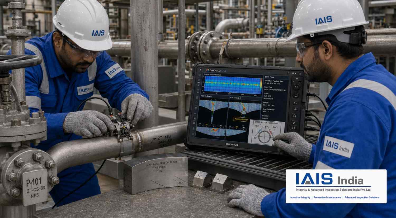
PAUT Inspection of Small-Diameter Pipe Welds
Phased Array Ultrasonic Testing of small-diameter pipe welds is a specialized nondestructive testing application requiring careful probe selection, contoured wedges, accurate scanning and validated inspection procedures.
PAUT can provide detailed examination of circumferential welds without using ionising radiation. However, the curvature, limited scanning area and thin wall of small pipes make the inspection more technically challenging than PAUT of larger-diameter piping.
Every application must therefore be evaluated according to pipe diameter, wall thickness, material, weld profile, access and applicable inspection code.
What Is Considered Small-Diameter Piping?
There is no single universal diameter defining small-bore or small-diameter piping for every PAUT application.
For practical inspection planning, pipes with an outside diameter of approximately 4 inches and below may require specialized arrangements.
The exact limitation depends on:
➤ Pipe outside diameter
➤ Wall thickness
➤ Probe and wedge dimensions
➤ Scanner configuration
➤ Weld width and reinforcement
➤ Available scanning distance
➤ Required beam coverage
➤ Surface condition
Very small or thin-wall pipes may require alternative probes, customized wedges or supplementary NDT methods.
Why Is Small-Diameter PAUT Challenging?
Pipe Curvature
A flat wedge placed on a small pipe may not maintain consistent contact. Poor contact can cause:
➤ Unstable coupling
➤ Signal loss
➤ Wedge rocking
➤ Inconsistent beam entry
➤ Incorrect positional information
➤ Reduced inspection repeatability
A contoured wedge matching the pipe outside diameter can improve contact and scanning stability.
Limited Scanning Area
Small-bore piping often contains nearby fittings, flanges, supports, elbows and branch connections. These may restrict probe movement on either side of the weld.
Thin Wall Thickness
In thin components, ultrasonic signals from the entry surface, weld root and back wall occur close together. This can make defect separation and interpretation difficult.
Beam Distortion
Pipe curvature can affect:
➤ Beam refraction
➤ Beam divergence
➤ Exit-point position
➤ Focal depth
➤ Sound-path calculation
➤ Inspection sensitivity
The equipment setup and scan plan must account for the actual pipe geometry.
Weld-Profile Interference
Excessive reinforcement, root penetration, misalignment and surface irregularities may produce geometric responses that can resemble discontinuity signals.
Typical Applications
Small-diameter PAUT may be used for:
➤ Process-piping circumferential welds
➤ Boiler tubes and header connections
➤ Steam piping
➤ Utility piping
➤ High-pressure piping
➤ Chemical and petrochemical piping
➤ Refinery shutdown inspection
➤ Power-plant piping
➤ Offshore and marine piping
➤ Repair welds
➤ Fabrication-shop quality control
➤ In-service weld inspection
Defects Detectable by Small-Bore PAUT
Subject to the validated technique, PAUT may detect:
➤ Lack of sidewall fusion
➤ Lack of root fusion
➤ Incomplete penetration
➤ Cracks
➤ Slag inclusions
➤ Root-profile irregularities
➤ Undercut
➤Service-induced cracking
➤Weld-repair defects
➤ Laminations near the weld area
Detection capability depends strongly on defect orientation, wall thickness, beam angle, probe frequency, surface condition and weld geometry.
Specialized PAUT Equipment
A small-diameter pipe inspection system may include:
➤ Compact PAUT instrument
➤ Small-footprint phased-array probes
➤ Miniature contoured wedges
➤ Low-profile encoded scanner
➤ Circumferential encoder
➤ Adjustable probe holders
➤ Calibration pipe or reference block
➤ Couplant delivery arrangement
➤ Weld-tracking mechanism
Compact probes such as A15-type arrays and scanners such as Cobra- or Ecoline-type systems may be considered where compatible with the diameter, thickness and inspection procedure.
Equipment selection must be based on demonstrated coverage rather than equipment size alone.
Importance of Contoured Wedges
The wedge should provide stable contact with the pipe surface. For small diameters, a wedge may require contouring to match the actual outside diameter.
The wedge configuration can affect:
➤ Ultrasonic coupling
➤ Refracted angle
➤ Beam exit point
➤ Probe stability
➤ Focal-law accuracy
➤ Circumferential positioning
➤ Inspection sensitivity
If different pipe diameters are involved, separate contoured wedges or validated diameter ranges may be required.
Scan-Plan Development
A weld-specific scan plan should demonstrate ultrasonic coverage of:
➤ Weld root
➤ Lower fusion faces
➤ Upper fusion faces
➤ Weld body
➤ Heat-affected zone
➤ Near-surface region
➤ Far-surface region
The scan plan should consider:
➤ Actual pipe outside diameter
➤ Nominal and actual wall thickness
➤ Weld preparation
➤ Root gap and land
➤ Weld cap dimensions
➤ Probe index position
➤ Wedge footprint
➤ Sectorial or linear-scan range
➤ Selected wave mode
➤ Skip distance
➤ Beam spread
➤ Focal depth
➤ Restricted scanning areas
Computer-generated coverage does not by itself prove inspection performance. The technique should be demonstrated using a suitable reference block containing representative reflectors.
Calibration Requirements
Small-diameter pipe inspection normally requires calibration using a pipe section or curved reference block representative of the component.
The calibration should verify:
➤ Material velocity
➤ Wedge delay
➤ Beam-angle response
➤ Sensitivity
➤Time-corrected gain
➤ Encoder distance
➤ Circumferential position
➤ Reference-reflector detection
➤ Near-surface and far-surface responses
➤ System repeatability
Using a flat calibration block for a highly curved component may not represent actual inspection conditions unless specifically permitted and technically justified.
Inspection Procedure
1. Review of Technical Information
Before mobilization, the inspection team reviews:
➤Pipe schedule
➤ Outside diameter
➤ Actual wall thickness
➤ Material grade
➤ Weld configuration
➤ Surface access
➤Applicable code
➤ Acceptance criteria
➤ Weld quantity
➤ Required examination coverage
2. Surface Preparation
The scanning surface should be reasonably smooth and free from:
➤ Weld spatter
➤Loose scale
➤ Heavy paint
➤ Rust
➤ Sharp projections
➤ Oil and excessive contamination
Surface preparation requirements should be agreed before inspection.
3. System Setup and Calibration
The probe, wedge and focal laws are configured for the actual pipe geometry. Calibration is completed using the approved reference block.
4. Circumferential Scanning
The probe or scanner travels around the weld while the encoder records its position. Depending on access and procedure requirements, scanning may be performed from one or both sides.
5. Data Analysis
The collected data are reviewed for:
➤ Indication position
➤ Indication length
➤ Through-wall location
➤ Signal response
➤ Relationship to weld geometry
➤ Evaluation against acceptance criteria
6. Reporting
The final report records the setup, calibration, scan coverage, indications, results and inspection limitations.
Encoded PAUT for Small Pipes
Encoded scanning records both ultrasonic information and the circumferential probe position.
Its benefits include:
➤ Permanent inspection data
➤ Weld-wise traceability
➤ Accurate indication positioning
➤ Repeatable scan speed
➤ Improved coverage monitoring
➤ Client and third-party review
➤ Comparison during future inspections
Scanner alignment is particularly important because minor positional changes can significantly affect coverage on a small-diameter pipe.
PAUT and TOFD for Small-Diameter Pipes
TOFD can be challenging on small-diameter or thin-wall piping because:
➤ Probe-centre separation is limited
➤ Curvature affects probe contact
➤ Lateral and back-wall dead zones may overlap
➤ Signals occur close together
➤ Scanner space is restricted
Combined PAUT and TOFD may still be possible for some pipe sizes, but technical feasibility must be demonstrated.
For very small or thin-wall components, PAUT alone or PAUT supported by another NDT method may provide a more practical approach.
Limitations of Small-Diameter PAUT
Potential limitations include:
➤ Insufficient scanning distance
➤ Inability to scan from both sides
➤ Closely positioned pipe fittings
➤ Weld reinforcement interference
➤ Poor wedge contact
➤ Beam distortion from curvature
➤ Limited near-surface resolution
➤ Thin-wall signal overlap
➤ Coarse-grained or attenuative materials
➤ Uncertain weld dimensions
➤ Restricted scanner clearance
➤ Inadequate calibration specimens
Where full coverage cannot be demonstrated, the limitation should be clearly reported to the client.
Information Required for Feasibility Review
Clients should provide:
➤ Pipe outside diameter
➤ Nominal and actual wall thickness
➤ Pipe schedule
➤ Material specification
➤ Weld-joint drawing
➤ Weld-cap dimensions
➤ Number of welds
➤Straight length available beside the weld
➤ Details of nearby elbows, flanges and supports
➤ Scanning access
➤ Applicable code
➤Acceptance criteria
➤ Site location
➤ Inspection schedule
Photographs of the weld and surrounding area are also highly valuable during the feasibility assessment.
Our Small-Diameter PAUT Capabilities
Integrity & Advanced Inspection Solutions India Private Limited provides specialized PAUT inspection support for small-diameter piping in refineries, petrochemical plants, power stations, fabrication facilities, offshore installations and industrial shutdowns.
Our capabilities can include:
➤Compact phased-array probes
➤ A15-type small-footprint probes
➤ Flat and contoured wedges
➤ Cobra- and Ecoline-type encoded scanners
➤ Customized wedge development
➤ Diameter-specific calibration blocks
➤ Weld-specific scan plans
➤ Encoded circumferential scanning
➤ Procedure preparation
➤ On-site data analysis
➤ Detailed weld-wise reporting
➤ PAUT feasibility demonstrations
Request a Small-Bore PAUT Assessment
Send your pipe dimensions, weld drawing, material specification, photographs, inspection quantity and applicable code to our technical team.
We will evaluate the available scanning space, probe configuration, wedge contour, calibration requirements and achievable weld coverage before recommending the final inspection technique.